
Geogrid for Retaining Walls: Design and Slope Checklist
By GeoTexGrid Engineering Team
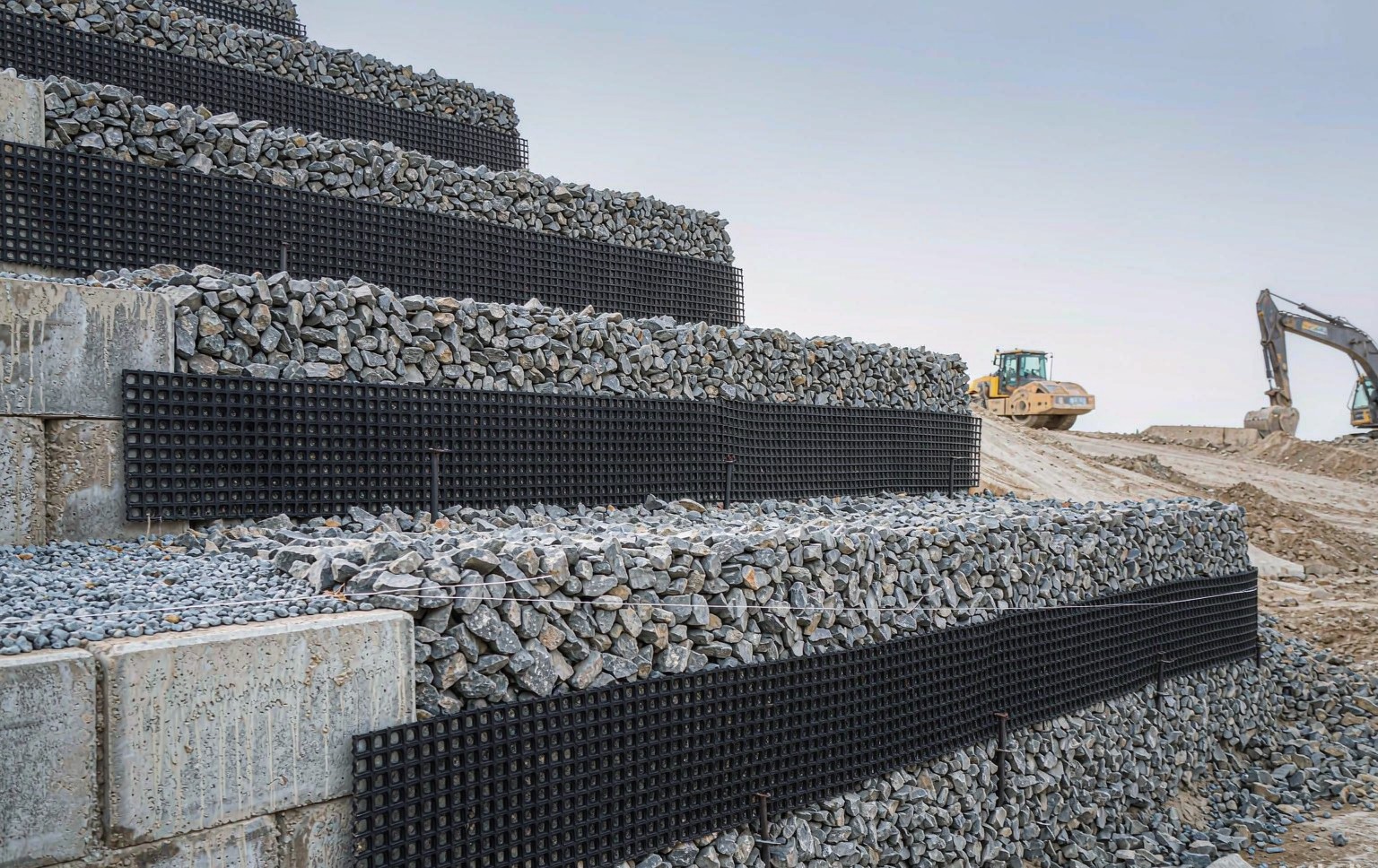
A geogrid reinforced retaining wall is a composite structure: granular fill, horizontal layers of geogrid, and a facing that holds the front edge together. Get the geogrid selection and layout right and the wall acts as a heavy, flexible gravity block. Get one checklist item wrong — usually the fill or the drainage — and even a strong geogrid cannot save it.
Why Geogrid Works in Retaining Walls and Steep Slopes
Soil is strong in compression but weak in tension. Reinforced soil fixes that: geogrid layers are buried in compacted fill, and the soil's own weight locks the ribs into the apertures through interlock and friction. Any tendency of the mass to slide outward is transferred into the geogrid as tension, which the geogrid carries back into the stable mass behind the failure plane. Against a conventional gravity or cantilever wall, a mechanically stabilized earth (MSE) structure with geogrid is typically 30–50% cheaper for walls above 4–5 m, tolerates differential settlement far better, and needs no formwork or curing time.
Uniaxial or Biaxial: Matching the Geogrid to the Structure
Wall geogrids are almost always uniaxial — high-strength in the machine direction, moderate in the cross direction — because the driving force acts in one direction: outward. Our uniaxial family runs 50–300 kN/m in the machine direction on an HDPE-coated steel-plastic core, tested to ASTM D6637 and GB/T 19274, with a custom aperture (≥ 100mm) so the ribs interlock with the specified fill.
| Product | Tensile strength | Aperture | Roll width | Roll length | Coating | Test standard |
|---|---|---|---|---|---|---|
| Steel-Plastic Uniaxial Geogrid | 50–300 kN/m | Custom (≥ 100mm) | 1.0 – 2.0 m | 30 – 100 m | HDPE | ASTM D6637, GB/T 19274 |
| Steel-Plastic Biaxial Geogrid | 30–150 kN/m | 12.7mm / 25.4mm / 38.1mm | 1.0 – 3.0 m (custom) | 30 – 50 m | HDPE / LDPE | ASTM D6637, GB/T 19274 |
| Self-Adhesive Fiberglass Geogrid | 30–80 kN/m | 12.7mm / 25.4mm | 1.0 – 2.0 m | by order | Pressure-sensitive | ASTM D6637, JTG E50 |
A wall offer quoted only in biaxial numbers is being quoted from the wrong table. Biaxial grades belong under roads and platforms, where wheel loads must spread in two directions — except on low walls and slope veneer reinforcement, where they are simply more economical.
The Design Checklist: Eight Items to Verify
| # | Checklist item | What to verify | Typical target |
|---|---|---|---|
| 1 | Reinforced fill quality | Select granular fill; limit fines and plasticity | Friction angle ≥ 34°, PI ≤ 6, ≤ 15% passing 0.075 mm |
| 2 | Geogrid strength | Long-term design strength (LTDS), not just ultimate | 50–300 kN/m uniaxial range (ASTM D6637); creep reduction per GRI-GG4 |
| 3 | Vertical spacing | Spacing vs facing type and compaction lift thickness | 0.2–0.4 m for segmental blocks; ≤ 0.8 m for wrapped face |
| 4 | Reinforcement length | Embedded length behind failure wedge | ≥ 0.7H, practical minimum about 2 m |
| 5 | Toe embedment | Burial depth below finished grade | H/10 level, up to H/4 at a 1.5H:1V toe slope; ≥ 0.6 m |
| 6 | Connection strength | Connection capacity ≥ local pullout demand | Per connection test report for the block/panel system |
| 7 | Drainage | No water pressure behind the reinforced mass | Free-draining fill, drain at the facing, chimney or geocomposite drain |
| 8 | Global stability | Deep-seated slip through or behind the zone | FS ≥ 1.3 static; ≥ 1.1 seismic |
Two of these decide most failures. The fill — geogrid and soil work as one material, so soft clay fill makes the composite weak no matter how strong the grid is; published design strengths assume AASHTO-type select fill with a friction angle of at least 34°. The drainage — water adds hydrostatic pressure the geogrid was never designed to resist and softens the retained soil at the same time; nearly every wall failure investigation finds water as a contributing cause. For soft foundations under high walls, check bearing and settlement separately — the ground conditions that call for geogrid soft soil stabilization under a road also apply at a wall toe.
Putting the Checklist Numbers on a Real Wall
Take a 6 m high segmental block wall on firm ground as a worked check — a typical project condition, not a specific job:
| Step | Calculation | Result |
|---|---|---|
| Reinforcement length | L = 0.7H = 0.7 × 6 m | 4.2 m (clears the 2 m minimum) |
| Number of layers | n = H ÷ spacing = 6 ÷ 0.4 m | 15 layers |
| Reinforcement area | 15 × 4.2 m² per metre run | 63 m² per metre of wall |
| Rolls required | 63 m² ÷ 60 m² (a 2.0 m × 30 m roll) | ≈ 1.05 rolls per metre run |
| Layers cut per roll | 30 m ÷ 4.2 m | 7 layers, 0.2 m offcut |
Strength is then zoned, because tension demand is highest at the base and falls toward the crest:
| Zone of a 6 m wall | Tension demand | Grade to start from (uniaxial range) |
|---|---|---|
| Bottom third, base to 2 m | Highest — full overburden, shortest pullout length | 200–300 kN/m |
| Middle third, 2–4 m | Moderate | 100–200 kN/m |
| Top third, 4–6 m | Lowest | 50–100 kN/m |
These are starting points for a design that must be checked by the project engineer against ASTM D6637 test data, the GRI-GG4 creep reduction, and the connection capacity of the chosen facing system — not a substitute for site-specific design. But a quotation that puts 100 kN/m material in the bottom third of a 6 m wall has told you something useful early.
Common Mistakes That Cause Wall Failures
- Clay fill and no drainage — the combination behind most collapses, usually after the first heavy rainy season.
- Spacing stretched to save material — doubling vertical spacing more than doubles the tension each layer carries, and thick lifts compact poorly.
- Connection ignored — the grid may be strong in soil but pull through or shear at the block, the weakest link in the system.
- Reinforcement not tensioned — slack grid contributes nothing until the wall has already deformed.
- Surcharge surprises — a parking area or stockpile behind the wall changes the design case. Quote the real surcharge.
Steep Slopes vs Vertical Walls: What Changes
On a steep slope (45° to 70°) the primary mode is a shallow surficial slip, so geogrid acts as veneer reinforcement: lighter grades at closer spacing, with a wrapped or vegetated face; primary reinforcement against deep-seated failure is added only where height or a weak foundation demands it. On a vertical MSE wall, internal stability (pullout and rupture), external stability (sliding and overturning) and connection capacity all carry design weight, and the facing system dictates connection testing and vertical spacing. Bulging at the face is almost always a spacing or connection problem, not a strength problem.
Installation matters as much as the drawing: strong direction perpendicular to the face, rolls butted rather than overlapped in the reinforcement direction, fill compacted in lifts that do not exceed the spacing. The geogrid installation guide for road reinforcement covers the same overlap and tensioning discipline.
Choosing the Right Geogrid for Your Project
- Product range and data sheets — Steel-Plastic Uniaxial Geogrid covers 50–300 kN/m at 1.0–2.0 m roll widths for walls and steep slopes, Steel-Plastic Biaxial Geogrid suits low walls and veneer reinforcement, or browse the full geogrid product range.
- Talk to an engineer — message us on WhatsApp with your wall height, slope angle and fill type for a same-day technical answer, or email cn8978688@gmail.com.
- Related reading — Biaxial vs Uniaxial Geogrid explains which direction of strength your structure needs.
GeoTexGrid manufactures uniaxial and biaxial steel-plastic geogrids for retaining walls, steep slopes and reinforced foundations, with test data supplied per shipment. Send your cross-section, wall height and design surcharge — you will get a confirmed specification and quotation, usually within one working day.
Related Articles
Fiberglass Geogrid China Supplier: Mesh and Coat
How to vet a fiberglass geogrid China supplier: mesh size, bitumen vs polymer coating, and the rib-count arithmetic that proves a 30-100 kN/m datasheet.
Woven Geotextile China Manufacturer: Slit Film
A woven geotextile China manufacturer explains slit film tapes, the grab-versus-wide-width trap, and how roll width changes the area you pay for.
Geocell China Manufacturer: Perforation Surface
Perforated or textured walls decide how a geocell drains and grips. A geocell China manufacturer explains wall options, weld QC and checks before order.