
Biaxial vs Uniaxial Geogrid: Which Direction Do You Need?
By GeoTexGrid Engineering Team
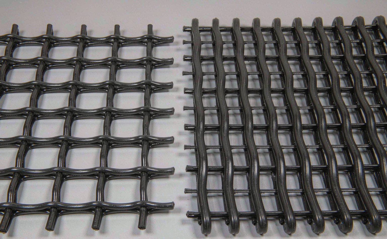
Specifying the wrong geogrid direction is one of the most expensive mistakes in soil reinforcement. A biaxial geogrid and a uniaxial geogrid may share the same polymer, the same aperture, and a similar price per square meter — yet they mobilise tensile strength along completely different load paths. Choose the wrong one and the reinforcement simply will not engage when the soil moves.
This guide covers the mechanical difference, where each belongs, and the data sheet values to check.
The Core Difference: Load Path, Not Strength
The distinction is not about how strong a geogrid is. It is about which direction that strength acts in.
- A biaxial geogrid develops high tensile strength in two perpendicular directions — machine direction (MD) and cross-machine direction (CMD) — at roughly equal magnitude.
- A uniaxial geogrid develops high tensile strength in one direction only. The ribs running perpendicular to that direction exist mainly to hold the aperture open and to anchor the grid in the soil.
Laid the wrong way round, a uniaxial grid behaves like a stiff net with almost no reinforcing effect in the critical direction — and the crew cannot tell by looking. Direction has to be fixed at design stage and marked on the drawing.
What Is a Biaxial Geogrid?
A biaxial geogrid is manufactured by punching and drawing a polypropylene or HDPE sheet into an integral grid. The drawing process orients the polymer molecules along both axes, producing a structure with:
- Near-symmetric tensile strength in MD and CMD (commonly 20–40 kN/m, higher grades up to 60 kN/m)
- A stiff, open aperture that interlocks mechanically with granular fill
- Excellent resistance to installation damage
- High junction efficiency, so load is transferred across the node rather than slipping at it
Biaxial geogrids work by confinement and interlock. The aggregate particles strike through the apertures, the grid restrains lateral movement, and the confined layer behaves as a stiffer, stronger composite.
Where Biaxial Geogrid Belongs
- Road base and sub-base reinforcement — the most common application worldwide
- Working platforms for piling rigs and crane pads
- Paved and unpaved haul roads
- Shallow soft soil stabilization, where lateral spreading is the failure mode
- Railway ballast reinforcement
- Parking areas, container yards, and hardstandings
If the load spreads radially and the soil wants to move in several directions at once, you need a biaxial geogrid.
What Is a Uniaxial Geogrid?
A uniaxial geogrid is engineered for a single, dominant load direction. It is typically produced from high-tenacity polyester or polypropylene yarns, or from steel wire coated in HDPE in the case of steel-plastic geogrids.
- Very high tensile strength along the load axis (commonly 40–300 kN/m)
- Low creep under sustained load when the polymer grade is correct
- Ribs perpendicular to the load axis are structural only
Uniaxial geogrids work by acting as a tensile tie. They resist the force that is trying to pull a soil mass downhill or outward, in the same way a rope holds back a load.
Where Uniaxial Geogrid Belongs
- MSE retaining walls — the grid ties the facing to the reinforced soil block
- Steep slope reinforcement, including wrap-around and veneer systems
- Embankment widening and bridge abutments
- Landfill liner and capping systems on slopes
- Void bridging and sinkhole remediation
- Reinforced soil slopes over soft foundations
In every one of these cases the soil mass wants to move in one direction: outward or downhill. A uniaxial geogrid placed along that direction works; a biaxial geogrid of the same weight would be far less efficient.
Side-by-Side Comparison
| Property | Biaxial Geogrid | Uniaxial Geogrid |
|---|---|---|
| Reinforcement direction | Two, perpendicular | One |
| Typical tensile strength | 20–60 kN/m (MD and CMD) | 40–300 kN/m (load axis) |
| Typical polymer | PP, HDPE | PET, PP, steel wire + HDPE |
| Load transfer mechanism | Confinement and aggregate interlock | Direct tensile tie |
| Primary failure mode resisted | Lateral spreading, rutting | Slope slip, wall overturning |
| Typical applications | Roads, working platforms, yards | Retaining walls, steep slopes, embankments |
| Critical installation risk | Insufficient aggregate cover | Grid laid in the wrong direction |
A Quick Decision Rule
Ask one question: is there a single direction the soil is trying to escape in?
- If yes → specify a uniaxial geogrid, orient it along the escape direction, and check creep and long-term design strength.
- If no, and the soil is spreading laterally under a distributed load → specify a biaxial geogrid, and check aperture size against your aggregate grading.
What to Check on a Geogrid Data Sheet
Whichever type you select, the numbers that matter are:
- Tensile strength at 2% and 5% strain — not just the ultimate value. Serviceability limits usually govern. Measured by ASTM D6637 for geogrids, or ISO 10319 on projects following European practice.
- Single-rib strength — ASTM D7737 isolates one rib, which is how long-term creep behaviour of uniaxial grids is characterised.
- Junction efficiency — the percentage of rib strength carried through the node. Values above 90% indicate a robust product.
- Creep reduction factor — applied when the reinforcement carries sustained load, particularly in walls and slopes.
- Aperture size — should be selected against the D50 of the fill so aggregate interlocks without passing through.
- Roll width, length, and roll weight — practical details that decide how fast your crew can lay it.
A supplier who cannot provide these values in writing, with the test method named, is not supplying an engineered product.
Real Grade Options From Our Production Line
The strength ranges quoted earlier describe the market in general. The table below is what we actually run — the same figures appear on our data sheets, tested to the methods listed:
| Product | Tensile Strength | Grid / Aperture Size | Roll Width | Roll Length | Test Standard |
|---|---|---|---|---|---|
| Steel-Plastic Biaxial Geogrid | 30–150 kN/m | 12.7mm / 25.4mm / 38.1mm | 1.0 – 3.0 m | 30 – 50 m | ASTM D6637, GB/T 19274 |
| Steel-Plastic Uniaxial Geogrid | 50–300 kN/m | Custom (≥ 100mm) | 1.0 – 2.0 m | 30 – 100 m | ASTM D6637, GB/T 19274 |
| Fiberglass Geogrid | 30–100 kN/m | 12.7mm / 25.4mm | 1.0 – 2.0 m | to project order | ASTM D6637, JTG E50 |
Note the jump from 150 kN/m to 300 kN/m. That is the difference between a grid you roll beneath a haul road and one you bury in a reinforced slope expected to perform for decades.
Failure Symptoms That Trace Back to a Direction Error
The symptoms cluster predictably, and each one points back to a specification decision:
| Observed symptom | Likely specification error | What to check first |
|---|---|---|
| Rutting develops despite an installed grid | Biaxial strength class below demand, or too-low modulus at 2% strain | ASTM D6637 load-strain curve vs. design assumption |
| Soil mass creeping downslope | Uniaxial laid across the load axis | Roll orientation against the design drawing |
| Panels tearing at overlaps in an MSE wall | Grid grade below T_required for the layer spacing | Required layer force vs. allowable long-term strength |
| Damaged grid visible after compaction | Cover depth or lift thickness below specification | First lift thickness and compactor type |
A Selection Check You Can Run Before Ordering
For reinforced slopes and walls, the demand on a single reinforcement layer is approximately:
T_required = Ka × γ × (H − z) × Sv
where Ka is the active earth pressure coefficient, γ the fill unit weight, H the reinforced height, z the depth of the layer below the crest, and Sv the vertical layer spacing.
What the grid can actually deliver is:
T_allowable = T_ult ÷ (RF_creep × RF_installation × RF_durability)
Run both. A higher-grade uniaxial product that satisfies T_required at wider spacing is frequently cheaper installed than several layers of a lower-strength grid — fewer layers means less placement labour and faster progress. Send us those two numbers with your drawing and we will confirm whether the quoted grade clears the check.
Get the Direction Right the First Time
Direction and grade are decided on paper, not on site — by then there is nothing left to inspect. Send drawing, subgrade CBR and design load, and our engineers will return the direction, grade, layout and quotation, usually within one working day.
Where to Go Next
- Product range and data sheets — see the full geogrid product range for tensile grades, aperture sizes and roll dimensions.
- Talk to an engineer directly — message us on WhatsApp for a same-day technical answer, or email cn8978688@gmail.com.
- Related reading — Steel-Plastic Geogrid vs Fiberglass Geogrid covers which polymer system suits which structure, while the geotextile selection guide explains the separation and filtration layer that usually sits beneath the base.
Related Articles
Fiberglass Geogrid China Supplier: Mesh and Coat
How to vet a fiberglass geogrid China supplier: mesh size, bitumen vs polymer coating, and the rib-count arithmetic that proves a 30-100 kN/m datasheet.
Woven Geotextile China Manufacturer: Slit Film
A woven geotextile China manufacturer explains slit film tapes, the grab-versus-wide-width trap, and how roll width changes the area you pay for.
Geocell China Manufacturer: Perforation Surface
Perforated or textured walls decide how a geocell drains and grips. A geocell China manufacturer explains wall options, weld QC and checks before order.