
Biaxial Geogrid for Road Base Reinforcement: Design Guide
By GeoTexGrid Engineering Team
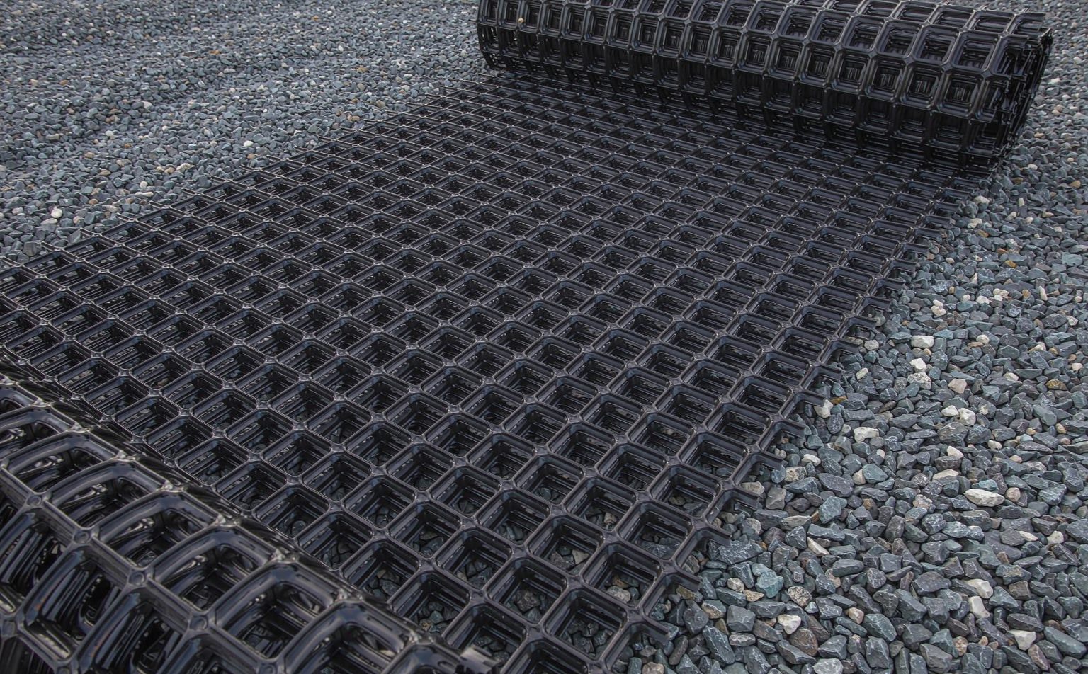
An unpaved haul road built on soft subgrade will rut within weeks if the load reaches the formation undiminished. A biaxial geogrid installed at the subgrade–base interface intercepts that load, confines the aggregate above it and spreads the stress wider. Used correctly it is one of the most cost-effective interventions in pavement engineering; used carelessly it is an expensive separator that does nothing structural at all.
What a Biaxial Geogrid Actually Does
A biaxial geogrid carries high tensile strength in the machine direction (MD) and cross-machine direction (CMD) at roughly equal magnitude, so it needs no orientation to a dominant load path. It reinforces by two mechanisms at once: lateral confinement — aggregate strikes through the apertures and the ribs restrain it from moving sideways, so the confined layer behaves as a stiffer composite — and tension membrane action, where the grid spans a locally settled void and carries part of the wheel load in tension. Two properties control both: aperture geometry must let the stone key in, and junction efficiency above 90% means each node transfers rib load without slipping, so the product acts as a true grid rather than a bundle of loose straps.
| Product | Tensile strength | Grid size / aperture | Roll width | Roll length | Coating or finish | Test standard |
|---|---|---|---|---|---|---|
| Steel-Plastic Biaxial Geogrid | 30–150 kN/m | 12.7mm / 25.4mm / 38.1mm | 1.0 – 3.0 m (custom) | 30 – 50 m | HDPE / LDPE | ASTM D6637, GB/T 19274 |
| Steel-Plastic Uniaxial Geogrid | 50–300 kN/m | Custom (≥ 100mm) | 1.0 – 2.0 m | 30 – 100 m | HDPE | ASTM D6637, GB/T 19274 |
| Fiberglass Geogrid | 30–100 kN/m | 12.7mm / 25.4mm | 1.0 – 2.0 m | by order | Bitumen / Polymer | ASTM D6637, JTG E50 |
| Self-Adhesive Fiberglass Geogrid | 30–80 kN/m | 12.7mm / 25.4mm | 1.0 – 2.0 m | by order | Pressure-sensitive | ASTM D6637, JTG E50 |
Read the first line carefully: our biaxial range runs 30–150 kN/m, tested to ASTM D6637. A quotation offering "biaxial 20 kN/m" is below the band we manufacture, and one offering "biaxial 200 kN/m" is quoting a uniaxial product — either way, ask for the test method before you compare.
Why Unreinforced Bases Fail
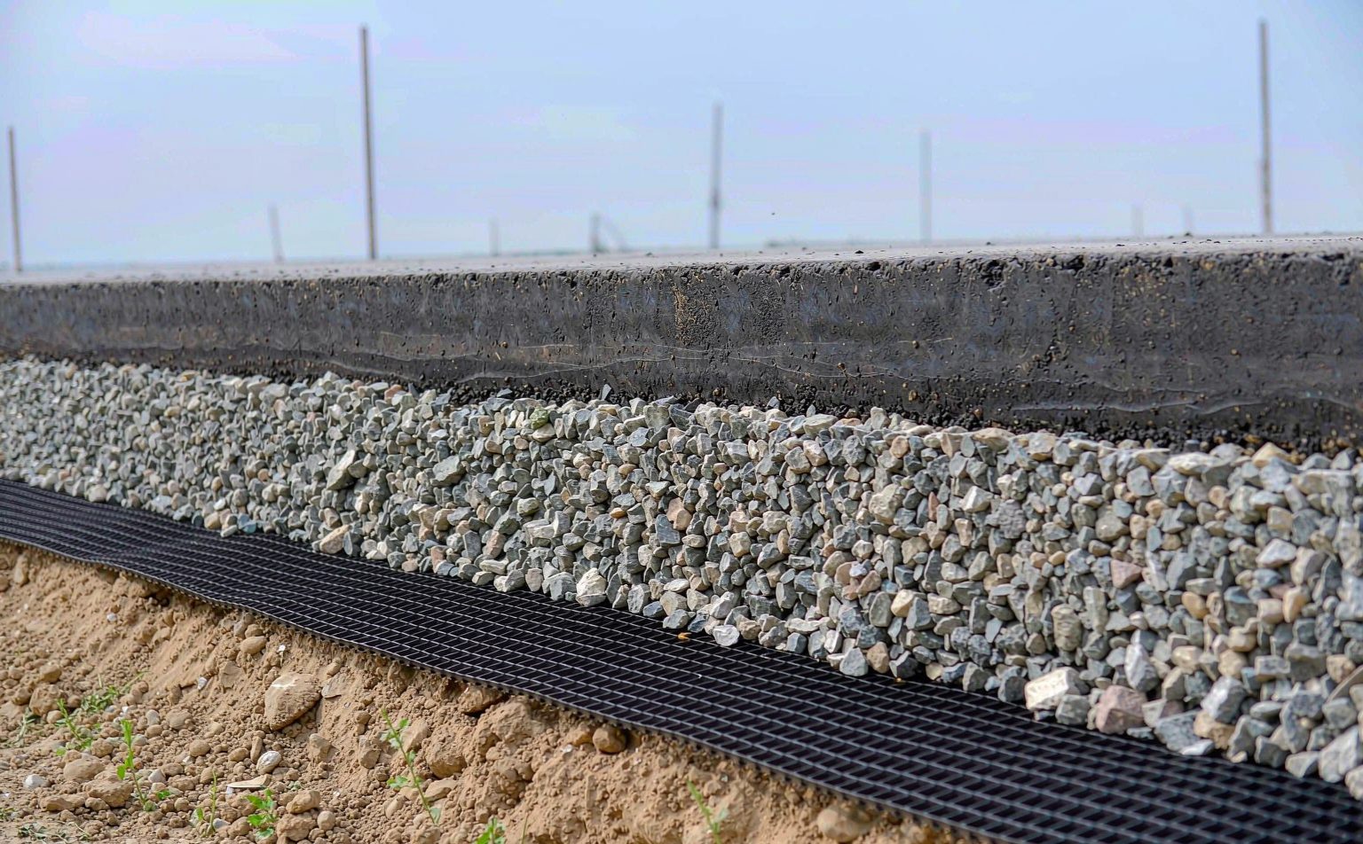
Most unpaved road failures on soft ground are not strength failures of the aggregate — the stone is fine. The subgrade beneath it fails in three predictable ways: bearing capacity failure, where a wedge of soil punches up into the base; lateral spreading, where aggregate is squeezed sideways under the wheel path and thins exactly where the load is heaviest; and fines pumping, where saturated subgrade fines migrate upward, contaminating the aggregate and destroying its drainage and stiffness.
The Three Design Inputs You Need
| Input | What it drives | Typical range |
|---|---|---|
| Subgrade strength (CBR or resilient modulus) | Reinforcement demand and base thickness | CBR 1–3% very soft; 3–8% soft |
| Design traffic (ESALs, axle load, tyre pressure) | Tensile grade and survivability | Haul roads often 10⁴–10⁶ ESALs |
| Base aggregate grading (D50, fines content) | Grid size selection | Well-graded crushed stone, low fines |
With these three, base thickness is designed by a recognised method — the Giroud–Han approach for unpaved roads is the most widely used — producing the two numbers designers care about: Traffic Benefit Ratio (TBR) and Base Course Reduction (BCR). Ask for TBR and BCR supported by test data, not marketing claims.
What the Thickness Reduction Looks Like
| Subgrade CBR | Unreinforced base | With biaxial geogrid | Approximate saving |
|---|---|---|---|
| 1% | 600–700 mm | 350–400 mm | 40–45% |
| 2% | 450–500 mm | 280–320 mm | 35–40% |
| 3% | 350–400 mm | 230–270 mm | 30–35% |
| 5% | 250–300 mm | 200–230 mm | 20–25% |
The saving shrinks as the subgrade improves — the honest reason to be sceptical of any supplier promising a fixed percentage regardless of site conditions.
Which Grade for Which Subgrade
Select on strength at 2% and 5% strain, not ultimate strength: serviceability, not rupture, governs road applications, and a high ultimate value with poor low-strain stiffness contributes very little in practice. Our biaxial range maps onto subgrade condition like this:
| Subgrade CBR | Duty | Grade to start from (30–150 kN/m range) |
|---|---|---|
| Below 1% | Very soft, membrane action dominant | 100–150 kN/m, plus a separation layer beneath |
| 1–3% | Soft haul roads and working platforms | 60–100 kN/m |
| 3–5% | Paved roads, yards, hardstandings | 40–60 kN/m |
| Above 5% | Marginal saving — check economics first | 30–40 kN/m |
Where the reinforcement carries sustained load — embankment bases, platforms left in place for years — apply the creep and installation-damage reduction factors before comparing grades, and confirm the figure comes from ASTM D6637 (multi-rib) rather than ASTM D7737 (single-rib), which reads higher.
Symptom-to-Spec Diagnosis
When a reinforced section underperforms, the failure mode tells you which line of the data sheet was wrong:
| What you see on site | What actually failed | Number to check before re-ordering |
|---|---|---|
| Rutting in the wheel path, stone pushed aside | Lateral spreading — confinement too weak | Strength at 2% strain (ASTM D6637); grid size vs D50 |
| Stone disappearing into the subgrade | Separation and fines pumping | Grid size vs D50; add a separation geotextile beneath |
| Grid torn at the rib junction | Junction efficiency too low | Junction strength as % of rib strength |
| Whole section settles evenly | Subgrade bearing, not a grid problem | CBR profile — reinforcement cannot fix bearing failure |
That last row is the one buyers most often miss: a geogrid confines and separates, it does not create bearing capacity. If the CBR profile is below about 1%, the design needs ground improvement or a thicker section, not a stronger grid.
Installation: The Details That Decide Performance
A correctly specified geogrid installed badly performs worse than a modest grid installed properly:
- Prepare and proof-roll the subgrade — deal with soft spots, ruts and standing water before the roll is opened.
- Lay with a minimum 300 mm overlap along roll edges in the direction of the ribs, wider on curves.
- Tension the grid and remove wrinkles — slack grid mobilises only after the soil has already moved.
- Place at least 150 mm of aggregate cover before compaction plant tracks onto the grid.
- Never dump aggregate from height onto an exposed grid, and avoid sharp turns under load.
Where Biaxial Geogrid Pays Back Fastest
Temporary and permanent haul roads over soft clay or peat; working platforms for piling rigs and cranes; paved roads with subgrade CBR below 5%; container yards, hardstandings and parking areas; railway ballast reinforcement; and bridging shallow voids without excavation. In all of them the failure mode is the same — load spreading radially, soil moving in more than one direction at once.
Choosing the Right Biaxial Geogrid for Your Project
- Product range and data sheets — Steel-Plastic Biaxial Geogrid covers 30–150 kN/m at 12.7 / 25.4 / 38.1 mm grid sizes for base reinforcement, Steel-Plastic Uniaxial Geogrid covers 50–300 kN/m where the load path is one-directional, or browse the full geogrid product range.
- Talk to an engineer — message us on WhatsApp for a same-day technical answer, or email cn8978688@gmail.com.
- Related reading — Steel-Plastic vs Fiberglass Geogrid for higher-demand applications, and the nonwoven vs woven geotextile guide for the separation layer beneath the base.
GeoTexGrid manufactures biaxial and uniaxial geogrids across the full range of base reinforcement grades, supplied to project width and roll length. Send your subgrade CBR, design traffic and aggregate grading — you will get a confirmed specification, thickness calculation and quotation, usually within one working day.
Related Articles
Fiberglass Geogrid China Supplier: Mesh and Coat
How to vet a fiberglass geogrid China supplier: mesh size, bitumen vs polymer coating, and the rib-count arithmetic that proves a 30-100 kN/m datasheet.
Woven Geotextile China Manufacturer: Slit Film
A woven geotextile China manufacturer explains slit film tapes, the grab-versus-wide-width trap, and how roll width changes the area you pay for.
Geocell China Manufacturer: Perforation Surface
Perforated or textured walls decide how a geocell drains and grips. A geocell China manufacturer explains wall options, weld QC and checks before order.